Pin Box Manager – software application for automation of schematic symbol generation for multi-pin components
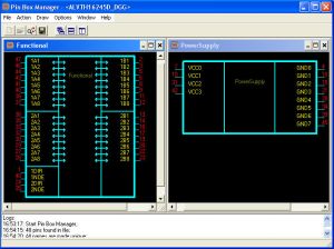 Pin Box Manager - Symbol Editor for Expedition PCB
|
Pin Box Manager (PBM) – software application for automation of schematic symbol generation for multi-pin components being imported to the central library of Expedition PCB by Mentor Graphics. The key feature of this application is symbol view conformance to the GOST, which makes schematic symbols to look better and simplifies the design process. PBM has a row of adjustable parameters which allow achieving exactly that graphic representation of the symbol that you planned. Pin Box Manager application provides import and export of the pinout table to the tab-delimited text so it simplifies multi-pin symbols creation such as for FPGA, including multi-symbol components.Features- Flexible parameters of component symbol representation on the schematic layout;
- Conformance to the GOST;
- Generation, editing, saving, import and export of the pinout table;
- Multi-symbol component support, functional groups and types provided by the CAD;
- Export:
- export to the central library of Expedition PCB software;
- export to the tab-delimited text file;
- Import:
- import from the tab-delimited text file;
- import of pinout table from the IBIS-model of the component;
- import from the schematic Design Capture/Design View (DC/DV) project.
DocumentationParameter | Value | Operating System | Windows XP | Current Version | 1.5 | | Last Modification Date | April 2007 г. | | Release Notes | | | User Manual | Pin Box Manager - User Guide |
PricingConditions | Variant, # | Trial | 1 | 2 | 3 | | Time Period | 1 week | 6 mon. | unlimited | unlimited | | Support | — | — | 1 year | 1 year | | Special modification on customer’s request* | — | — | — | 1 year | | Price | $0 | $100 | $320 | $1 200 |
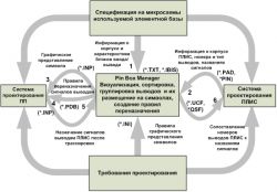
*Any modification is possible if it is not in conflict with architecture of the application. IntroductionOne of the necessary stages of the PCB design workflow is creation and supplement of the component library. Each library component consists of the text properties (such as IC description, Part Number, Part Name, etc.), footprint, symbol and special table that states the correspondence between Pin Numbers in the footprint (cell) and Pin Names in the symbol. As the components are being added to the library permanently so there is a need in automation of this process. In addition to this, when multi-pin components are being added manually, there is a significant possibility of error in pinout table. The errors of this kind are hard to detect and they are revealed only when the PCB is already assembled and tested. The functionality of the PBM are presented in the fig. 1.
 PBM Design Flow
| | Fig.1. PBM Functionality |
Symbol Creation in PBM (Pin Box Manager)The first step of symbol creation is defining the Pin Name list and pinout table, i.e. correspondence between Pin Names and Pin Numbers. There’re three ways to get the table: - first one – to import pinout table from IBIS model supplied by the vendor of the IC you want to add;
- second – to import table from datasheet or some CAD file (for FPGA) via copy&paste to the tab-delimited text, where left column is the Pin Name and the right (second) – Pin Number (optional). You can also have the third auxiliary column – Pin Type;
- third – to add pins manually in PBM.
After the pin list has been got, PBM application automatically finds all pins with equal Pin Names and makes them unique. It is necessary as the library doesn’t support pins with the same name as it’s the key property in the library’s database. After that, the remaining process is divided into three steps: - Grouping the pins with identical functionality, like VCC or GND pins, address bus, etc.
- Creation one or several Symbol Names (for multi-symbol components);
- Arrangement of the created groups in each symbol with given Symbol Name.
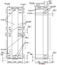
While arrangement of the pins within symbol it’s convenient to work exactly with groups because to place pins individually is labor intensive process, and in group you usually have a lot of pins so the number of groups is quite small. You can create as many groups as you want, also you can sort pin within group by Pin Name, Pin Type, Pin Number.The final step is to make the symbol look in schematic layout as you want to. There’re many adjustable parameters to do it (see fig. 2)
 PBM Parameters
| | Fig. 2. PBM Symbol Parameters |
ExampleThis example illustrates the creation of symbol for ALVTH16245D chip. The IC has 48 pins, which were imported from IBIS model downloaded from the vendor site. The IC represents buffer with two 8-bit data buses, four control inputs, and power pins.
 PBM Pin Groups
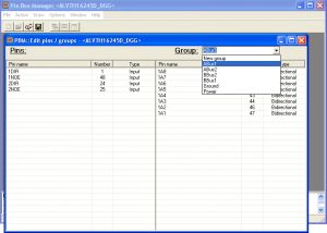
| | Fig. 3. PBM Pin Groups |
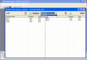
Let’s create groups for data bus, control, and power pins as shown in fig. 3. At the level column pins not included in any group are being displayed, at the right – pins included in the selected group. As a result we got 7 groups, which have to be arranged within symbol. Let’s create two symbols for this component: first for power pins, second – for the others. First symbol we name “Power Supply”, second – “Functional”, fig. 4. (It should be noted that in real practice they would be named with prefix like ALVTH16245D_ to distinguish these symbols from others in the library.)
 PBM Multi-symbol
| | Fig. 4. PBM Multi-symbol |
Now you can preview the symbols, fig. 5. They are ready for the export to the library.
 Pin Box Manager - Symbol Editor for Expedition PCB
| | Fig. 5. PBM Symbol Preview |
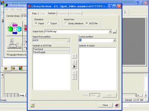
To do it you have to export them to the .inp format first. Then launch the Library Manager, open Library Services and select Symbols tab, select Import and ASCII radio-buttons, select the Partition you want to import to, and select the .inp file as shown in the fig. 6, press Apply button.
 Import from PBM to the central library
| | Fig. 6. Import to the central library |
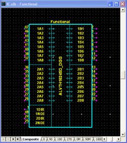
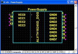
All done. Now you can view your symbols in the library and check the result in Symbol Editor tool (7, a, b).
 Symbol preview
|
 Symbol preview
| | Fig. 7,a. First symbol (view in Symbol Editor) | Fig. 7, b. Second symbol (view in Symbol Editor) |
|