RF Synthesizer 62.5MHz – 8GHz with output level up to +0dBmWideband frequency synthesizer (RF Signal Generator) with output frequency range from 62.5 MHz to 8 GHz with small frequency step. Output power is variable and AGC controlled with digital compensation system based on calibration data written in memory of the device. Synthesizer also has multi-path filtering block for additional harmonic suppression. Device is digitally controlled via SPI interface. Frequency tuning can be dynamically programmed within all specified frequency range. This device represents the modification of the LNO-HP02M-RF with slight difference in output stages. The main feature of this device is its low cost due to significant decrease of the output stage power.
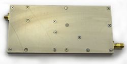 RF Synthesizer 62.5 MHz - 8 GHz, +0 dBm
|
Features- Low cost;
- RF output frequency range: 62.5 MHz – 8 GHz;
- Min. frequency step: ≈1 Hz (@1 GHz);
- Harmonic levels: less than -40 dBc (@ 0.25 8 GHz).
Pricing and AvailabilityPrice1, (@ qty.) | Stock qty.2 | Time3 | 1 | >1 | Delivery | Production | $3 100 | call | 0 | 2 weeks. | 1.5–2 mon. |
- It’s a guiding price, for more information contact us.
- Only discrete parts quantity is shown (some of the devices may be already included in other systems as a part), for more information contact us.
- Delivery time — if product is available in the stock, production time — otherwise.
Product componentsItem | Components | Qty. | Description | 1 | LNO-LP01M-RF | 1 | Wideband frequency synthesizer 62.5 MHz – 8 GHz. Low-cost variant |
Accessories№ поз. | Компоненты | Кол-во | Описание | 1 | RS2SPI-01M-PCB | 1 | Evaluation board for RF-blocks with SPI-interface (like this) control via COM-port (RS-232) of the PC. This board serves as a RS-232 to SPI bridge | 2 | RF Debug Application | 1 | Software application for RF-blocks control via PC COM-port. Application has open source as it is written on Tcl/Tk and is used for easy learning of SPI control commands for particular RF-block, and for further integration of the block into user’s own complete system |
Notes: accessories are not included in the product above, they should be ordered separately. With aid of LNO synthesizer, RS2SPI board and RF Debug software one can easily assemble low-cost single or double RF-signal generator for test and measurement needs. You can learn more about it in the “How to assemble Low-cost RF-Signal Generator” article in the “Application Notes” section. DocumentationFile | Type | Description | | LNO-HP01M-P3U4HP220E - 3D Model | pdf | 3D-model of the Pi-U including RF-block (one can hide the details not relating to the block) | | LNO-HP(LP)01(02)M-RF - Assembly Drawing | pdf | Assembly Drawing and BOM | | LNO Datasheets | ref | Documentation: programming user guide, interfaces specs, control commands and etc. |
Additional documentation is available in the appropriate section for registered users. Download search system may be useful in this case.
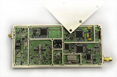 RF Synthesizer (cover opened)
|
Specification| Parameter | Conditions | Value | Unit | | min | max | RF Output & General Characteristics | | RF Output Frequency Range | | 62.5 | 8000 | MHz | | Min. Frequency Step | (Fref=150MHz), @ Fout, MHz: | | | | | 62.5-125 | | 0.2 | Hz | | 125-250 | | 0.4 | Hz | | 250-500 | | 0.8 | Hz | | 500-1000 | | 1.6 | Hz | | 1000-2000 | | 3.1 | Hz | | 2000-4000 | | 6.2 | Hz | | 4000-8000 | | 12.4 | Hz | | Output Power Min. Range | @Fout=100MHz to 8GHz | -30 | +0 | dBm | | Output Power Min. Step Size | | | 0.1 | dB | | Nominal Output Impedance | | 50 | Ohm | | Output VSWR | | | 2.1 | | | Spectral Purity & Phase Noise Characteristics | | Phase Noise | Fout=1GHz, @ Offset: | | | | | 1kHz | | -95 | dBc/Hz | | 10kHz | | -105 | dBc/Hz | | 100kHz | | -100 | dBc/Hz | | 1MHz | | -125 | dBc/Hz | | Spurious Suppression | (except harmonics) | | -65 | dBc | | Harmonic Suppression | from 250MHz to 8GHz Fout | | -40 | dBc | | Internal Frequency Reference Characteristics (TCXO) | | Frequency | | 150 | MHz | | Temperature Stability | | ±2.5 | ppm | | Aging First Year | | ±1 | ppm | | Operating Temp. Range | | -40 | +65 | ºC | | Programming Interface (SPI, LVTTL 3.3V, 5V tolerant) | | Vih | | 2.0 | 5.5 | V | | Vil | | -0.5 | 0.8 | V | | Clock Frequency | | | 1 | MHz | | Power Supply | | +5VA Supply Voltage Current | | | 1.2 | A | | +9VA Supply Voltage Current | | | 0.6 | A | | -5VA Supply Voltage Current | | | 0.06 | A | | Dimensions | | Length | excluding SMA connectors | | 185 | mm | | Width | | | 87.5 | mm | | Height | | | 12.5 | mm |
Output FrequencyOutput frequency is given by the following equation Fout=(M/N)·Fref , where Fref — reference oscillator frequency (int. 150 MHz), N — integer in range from 0 to 232 (provided that Fout is in range given by the table below), M — constant integer given by the following table for each appropriate frequncy range. 62.5-125MHz | 125-250MHz | 250-500MHz | 0.5-1GHz | 1-2GHz | 2-4GHz | 4-8GHz | 229 | 230 | 231 | 232 | 233 | 234 | 235 |
Spectrum Diagrams
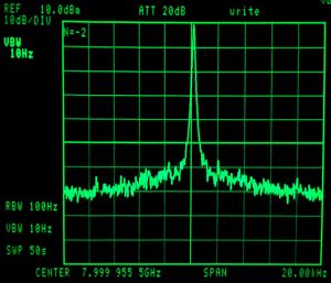 Phase Noise @ 8 GHz, 10 kHz Offset
|
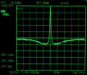 Phase Noise @ 8 GHz, 100 kHz Offset
|
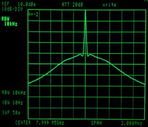 Phase Noise @ 8 GHz, 1 MHz Offset
|
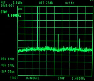 Spurious and Harmonic Rejection @ 1 GHz fundamental
|
|