How to Assemble and Effectively Use a Low-cost RF Signal Generator
 Low-cost RF Signal Generator based on LNO synthesizer
|
High frequency generator for RF engineer is of the same necessity as the spectrum analyzer. There is a standard row of problems encountered while debugging and testing. And almost alfl of them require the source of high-frequency test signal. But available models on the market (with band up to 3 or 6 GHz), including used equipment, cost no less than spectrum analyzers with the same frequency range. At the same time, the most of the tasks arising while the debugging and testing don’t require any ultrahigh characteristics, which should be paid for in the case of expensive equipment. Thereby there is a need in simple and low-cost, yet with good enough characteristics, solution enabling measurements of the key parameters of the device under test.
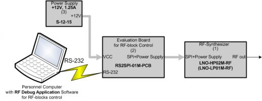
LNO-HP(LP)+RS2SPI SolutionAs a low-cost solution we suggest the kit with the following blocks (fig. 1):
 RS2SPI and LNO synthesizer connection diagram
| | Fig. 1. RS2SPI Evaluation board and LNO Synthesizer connection block diagram |
- RF-Synthesizer LNO-HP02M-RF (up to +20 dBm) or LNO-LP01M-RF (up to +0 dBm);
 RF Debug Application (LNO tab)
|
- Evaluation board RS2SPI-01M-PCB for RF-blocks control with aid of personal computer via COM-port, plus software (RF Debug Application);
- Power supply block S-12-15 or any other laboratory source with 12 V DC.
The cost of this kit is less than $3500 (February, 2009) and actually replaces full valued device. The key parameters of this solution are listed below: - RF output frequency range: 62.5 MHz – 8 GHz;
- Frequency step: about 1 Hz (@ 1 GHz);
- AGC-controlled output level range: from -10 to +20 dBm;
- Phase noise: -105 dBm @ 10 kHz offset from 1 GHz central.
Software included in the kit is written on Tcl/Tk language and so open sourced. This enables for user to grow a new functionality of the device, making changes in the existent code for their own. For example you can easily make frequency or amplitude sweeping in according to your own algorithms. This approach significantly extends the scope of application in testing and debugging. Which parameters can be measured with aid of LNO-HP(LP)+RS2SPI kit
 How to Make a Low-cost RF Signal Generator
|
Below in the order of significance are listed the minimum available parameters which could be done having one (in some cases two) ordinary scalar signal generators without any modulation.- Gain and frequency response of the RF-path measurements. After DC power supply testing it’s rather the first part of the debugging to find out if the RF stage is correct.
- Linearity parameters and maximum output power measurements for the output stages. These are one-decibel compression point (P1dB), two-tone second and third-order intercept points (IP2 and IP3), maximum saturated output power (Psat) measurements. Parameters of nonlinear distortion are very important to the digital communication systems, as they have impact on the workability of given modulation type at specified output signal level.
- The use as the local oscillator (LO) while debugging frequency converter’s path.
- Noise figure (NF) and sideband suppression measurements.
- Phase noise of the frequency converter’s path measurements.
- Input VSWR measurements.
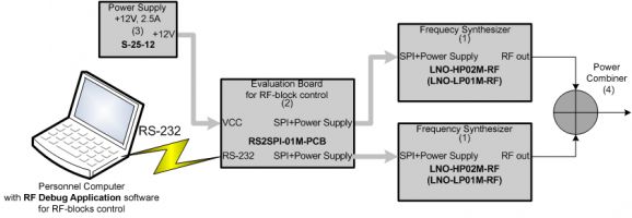
About particular methods of mentioned measurements you can find out in our former articles in the “App Notes” section on our web-site. Nonlinearity distortion measurementsFigure 2 shows block diagram for two-tone third order intercept point (IP3) measurements.
 Connection block diagram for IP3 measurements
| | Fig. 2. Connection block diagram for IP3 measurements |
In this case two LNO-HP synthesizers are being connected to the RS2SPI evaluation board, and output signals from them are being supplied to the power combiner (4). Such combiner you can find in Mini-Circuits. It’s passive device with relatively low cost. This way you can form clear two-tone signal with total power up to +23 dBm! Price comparisonThe table below represents some devices close to the suggested solution in parameters and cost, which are available on the market. Part Number | Freq. Range | Freq. Step | Phase Noise @ 1GHz | max. Pout | Price* | Description** | R&S SMA-100A (SMA-B106) | 9 kHz - 6 GHz | <1 Hz | -135 dBc/Hz @20 kHz | +18..+28 dBm | $30 000 | New equipment (eworld.ru) | | Gigatronics 12720A | 10 MHz - 20 GHz | <1 Hz | -103 dBc/Hz @10 kHz | +25 dBm | $20 000 | Used equipment (elvira.ru) | | Anritsu MG3681A | 9 kHz - 3 GHz | <1 Hz | -112 dBc/Hz @20 kHz | +25 dBm | $12 800 | Used equipment (elvira.ru) | | Hittite HMC-T200 | 700 MHz - 8 GHz | 1 MHz | -80 dBc/Hz @100 kHz | +10 dBm @8GHz | $4 000 | New equipment (hittite.com) | | LNO-HP Eval Kit | 62.5 MHz - 8 GHz | ~1 Hz | -105 dBc/Hz @10 kHz | +20 dBm | $3 800 | LNO-HP + RS2SPI | | LNO-LP Eval Kit | 62.5 MHz - 8 GHz | ~1 Hz | -105 dBc/Hz @10 kHz | +0 dBm | $3 400 | LNO-LP + RS2SPI |
* This research was originally made for Russian market for November, 2008. Approximate prices are presented. We think that real prices in other countries are of the same order.
** Red color indicates some kind disadvantages relative to variants in yellow-labeled rows; green color indicates benefits with respect to the same ones.
|