Vector Signal Generator up to 4 GHz
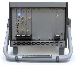
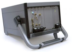
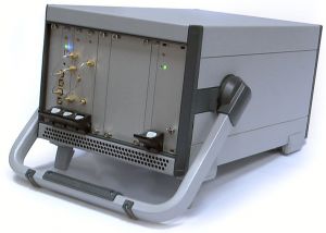
 VG4-01M-C42HP3U375A - Vector Signal Generator
|
RF vector generator is used for generation of the signal in form Re[(I(t)+jQ(t))ejωt], fwhere I(t) and Q(t) – sampled interval of quadrature signals (i.e. complex signal), written in device memory, ω – carrier frequency. On the front panel all intermediate signals are available for user – i.e. I and Q channels, local oscillator (LO) and output signal RF. Vector signal generator is controlled via USB port of a personal computer.Features- RF output frequency range: 0.1 – 4 GHz (in vector mode), 62.5 – 8 GHz (in scalar mode);
- RF output level tuning range: -10..+10 dBm (in vector mode), -30..+0 dBm (in scalar mode);
- Modulation types: QAM, PM, FM and all its modifications;
- Baseband: 66 MHz;
- Hardware interpolation: up to 4096;
- Hardware NCO with 32-bit phase and frequency control;
- Hardware phase and frequency digital modulation;
- Control interface: USB 2.0.
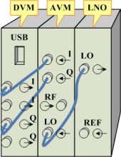
 Connection of modules in the VG4 vector generator
| Fig.1. Pi-U Connection diagram |
For more information about technical specifications see the documentation on the modules (plug-in units) which the generator consists of (see Product Components table). DescriptionVector signal generator VG4 has modular architecture based on the FXP bus and consists of the following functional plug-in units (Pi-Us): I/Q Baseband Generator – DVM Pi-U; Analog Quadrature (Vector) Modulator – AVM Pi-U; RF Frequency Synthesizer – LNO Pi-U, forming LO signal for the AVM block.
Interconnection diagram is shown in the fig. 1. Each of the plug-in units shown can also be used independently. For this reason all necessary connectors are available on the front panel. Pricing and AvailabilityPrice1, (@ qty.) | Stock qty.2 | Time3 | 1 | >1 | Delivery | Production | $9 740 | call | 1 | 2 weeks. | 1.5-2 mon. |
- It’s a guiding price, for more information contact us.
- Only discrete parts quantity is shown (some of the devices may be already included in other systems as a part), for more information contact us.
- Delivery time — if product is available in the stock, production time — otherwise.
Product components Item | Components | Qty. | Description | 1 | FXPPLM-01AIR-C42HP3U375 | 1 | FXP-based platform. Case – ratiopacPRO air, Schroff, std. IEEE 1101.10, dimensions 3/4U, 42HP, 375.5 mm | 2 | DVM-01M-P3U4HP220 | 1 | I/Q Baseband Generator plug-in unit | 3 | LNO-LP01M-P3U4HP220E | 1 | RF Synthesizer plug-in unit, 62.5 MHz – 8 GHz, +0 dBm (low-cost modification) | 4 | AVM4-01M-P3U4HP220E | 1 | Analog Vector Modulator plug-in unit with 0.1 to 4 GHz frequency range | 5 | FXPPSU-02M-P3U8HP220 | 1 | Power Supply Unit (AC-DC converter), 125 W | 6 | VG4 Pi-U SMA-SMA Rigid Cable | 3 | Rigid cable assembly for connections between AVM and DVM (I/Q channels) and LNO (LO signal). Type SMA-SMA |
Accessories № поз. | Компоненты | Кол-во | Описание | 1 | FXP Plug-in units | 1 | Functional plug-in units with FXP interface | 2 | USB-FXP Debug Application | 1 | Software application for RF-blocks control via PC COM-port. Application has open source as it is written on Tcl/Tk and is used for easy learning of SPI control commands for particular RF-block, and for further integration of the block into user’s own complete system |
Notes: accessories are not included in the product above, they should be ordered separately.
 VG4-01M-C42HP3U375A - Vector Signal Generator
|
 VG4-01M-C42HP3U375A - Vector Signal Generator
|
ApplicationsVector Signal Generator allows to solve the following problems: - debugging of receiver blocks of communication systems;
- analysis and debugging of hardware demodulation algorithms;
- analysis of the noise immunity and stability of the digital communication systems.
As for the first task – one can debug frequency conversion path both in the transmitting block (directly connecting I and Q outputs from DVM to the design under test) and the general operation of the receiving part, generating the signal with required modulation at the AVM RF output. As for the second task – vector generator besides forming the required signal can also simulate the following effects: - additive noise with arbitrary spectral density and probability characteristics;
- carrier phase noise with specified spectral density;
- deviation and phase offset of carrier and symbol frequency;
- quadrature phase error;
- mutual I and Q time offset.
As for the third task – VG4 allows to form a noise interference signal with specified characteristics for the stability analysis of the digital communication systems. |