|
AVM7-01M-RF - I/Q Modulator |
 |
 |
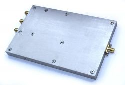
I/Q Modulator 4 – 7 GHz
 AVM7-01M-RF - I/Q Modulator
|
Wideband quadrature modulator (RF Vector Modulator) has three inputs – I, Q cannels and LO input, and one output – RF. This modulator has internal multi-path output filtering block and AGC-controlled output level. Device control is implemented by means of SPI interface. In conjunction with DVM plug-in unit (baseband generator) and synthesizer as a local oscillator quadrature I/Q modulator forms vector signal generator.Features- RF output frequency range: 4 – 7 GHz;
- Baseband: 300 MHz;
- RF output level range: -10..+10 dBm;
- Output filtering.
Pricing and AvailabilityPrice1, (@ qty.) | Stock qty.2 | Time3 | 1 | >1 | Delivery | Production | $1 390 | call | 0 | 2 weeks. | 1.5–2 mon. |
- It’s a guiding price, for more information contact us.
- Only discrete parts quantity is shown (some of the devices may be already included in other systems as a part), for more information contact us.
- Delivery time — if product is available in the stock, production time — otherwise.
Product componentsItem | Components | Qty. | Description | 1 | AVM7-01M-RF | 1 | I/Q signal modulator with output frequency range from 4 to 7 GHz and 300 MHz baseband, AGC-controlled output power, digital control via SPI-interface |
AccessoriesItem | Components | Qty. | Description | 1 | RS2SPI-01M-PCB | 1 | Board for RF-block with SPI-interface control via PC RS-232 port | 2 | RF Debug Application | 1 | Software application for RF-blocks control via PC COM-port. Application has open source as it is written on Tcl/Tk and is used for easy learning of SPI control commands for particular RF-block, and for further integration of the block into user’s own complete system |
Notes: accessories are not included in the product above, they should be ordered separately. DocumentationFile | Type | Description | AVM4(7)-01M-P3U4HP220E - 3D-Model | pdf | 3D-model of the Pi-U including RF-block (one can hide the details not relating to the block) | AVM4(7)-01M-RF - Assembly Drawing | pdf | Assembly Drawing and BOM |
Additional documentation is available in the appropriate section for registered users. Download search system may be useful in this case.
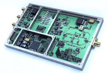
 I/Q Modulator 4 – 7 GHz (cover opened)
|
Specification| Parameter | Conditions | Value | Unit | | min | max | RF Output & General Characteristics | | RF Output Frequency Range | | 4000 | 7000 | MHz | | Output Power Min. Range | @Fout=4GHz to 7GHz | -10 | +10 | dBm | | Output Power Min. Step Size | | | 0.5 | dB | | Nominal Output Impedance | | 50 | Ohm | | Output VSWR | | | 2.0 | | | Output IP3 | | +30 | | dBm | | Output P1dB | | +16 | | dBm | | I/Q Characteristics | | Sideband Suppression | 4-5GHz | 32 | | dB | | 5-7GHz | 22 | | dB | | Carrier Suppression | calibrated | 40 | | dB | | I or Q Port Bandwidth | -3 dB Cutoff | DC | 150 | MHz | | LO Port Characteristics | | Frequency | | 4000 | 7000 | MHz | | Nominal Output Impedance | | 50 | Ohm | | Input VSWR | | | 1.4 | | | Programming Interface (SPI, LVTTL 3.3V, 5V tolerant) | | Vih | | 2.0 | 5.5 | V | | Vil | | -0.5 | 0.8 | V | | Clock Frequency | | | 1 | MHz | | Power Supply | | +5VA Supply Voltage Current | | | 0.2 | A | | +9VA Supply Voltage Current | | | 0.1 | A | | -5VA Supply Voltage Current | | | 0.05 | A | | Dimensions | | Length | excluding SMA connectors | | 135 | mm | | Width | | | 87.5 | mm | | Height | | | 12.5 | mm |
|
|
|