|
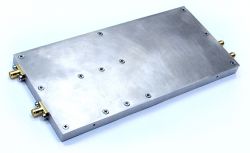
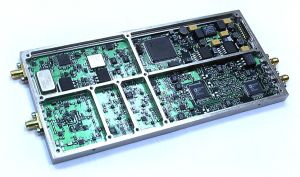
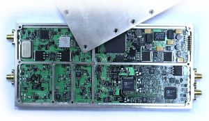
AVD2-01M-RF - I/Q Demodulator |
 |
 |
I/Q Demodulator 700 – 2700 MHz
 AVD2-01M-RF - I/Q Demodulator 0.7 - 2.7 GHz
|
RF vector demodulator (I/Q demodulator) has multi-path filtering block at I and Q outputs, double AGC loop with embedded detector before quadrature mixer to provide linear operation while high-level sideband interferences. Demodulator has internal local oscillator (synthesizer) and reference. Optional external reference clock input is also provided. Features- Linearity: IMD3 < -50 dB;
- Baseband: 100 MHz;
- Gain range: 110 dB;
- Multi-path I/Q filtering for better narrow band performance.
Pricing and AvailabilityPrice1, (@ qty.) | Stock qty.2 | Time3 | 1 | >1 | Delivery | Production | $2 750 | call | 0 | 2 weeks. | 1.5–2 mon. |
- It’s a guiding price, for more information contact us.
- Only discrete parts quantity is shown (some of the devices may be already included in other systems as a part), for more information contact us.
- Delivery time — if product is available in the stock, production time — otherwise.
Product componentsItem | Components | Qty. | Description | 1 | AVD2-01M-RF | 1 | RF I/Q demodulator with input frequency range from 700 MHz to 2.7 GHz and 100 MHz baseband, with digital control via SPI interface |
AccessoriesItem | Components | Qty. | Description | 1 | RS2SPI-01M-PCB | 1 | Board for RF-block with SPI-interface control via PC RS-232 port | 2 | RF Debug Application | 1 | Software application for RF-blocks control via PC COM-port. Application has open source as it is written on Tcl/Tk and is used for easy learning of SPI control commands for particular RF-block, and for further integration of the block into user’s own complete system |
Notes: accessories are not included in the product above, they should be ordered separately. DocumentationFile | Type | Description | AVD2-00M-P3U4HP220E - 3D-Model | pdf | 3D-model of the Pi-U including RF-block (one can hide the details not relating to the block) | AVD2-01M-RF - Assembly Drawing | pdf | Assembly Drawing and BOM |
Additional documentation is available in the appropriate section for registered users. Download search system may be useful in this case.
 AVD2-01M-RF - I/Q Demodulator 0.7 - 2.7 GHz
|
 AVD2-01M-RF - I/Q Demodulator 0.7 - 2.7 GHz
|
Specification| Parameter | Conditions/subparameters | Min | Max | Unit | | Frequency | | Frequency range | | 700 | 2700 | MHz | | Frequency resolution | | | 0.01 | Hz | | Frequency accuracy | T=0..+70oC | | ±10 | ppm | | External reference | | 100 | MHz | | Input Resistance | 50 | Ω | | Input level | 1 | | V | | Synthesizer setting time | (any step width) | | 5 | ms | | Phase noise* | @1GHz, @Offset (Hz):
100
1k
10k
100k
1M |
-100
-115
-115
-110
-130
|
dBc/Hz
dBc/Hz
dBc/Hz
dBc/Hz
dBc/Hz | | RF Input | | Input Resistance | | 50(75 optional) | Ω | | Input level | normal operation | -110 | 0 | dBm | | nonlinear | +10 | | dBm | | Maximum composite signal level | normal operation | | +35 | dBc | | nonlinear | | 0 | dBm | | Gain Control | total range | 110 | | dB | | step size | | 1 | dB | | VSWR @50Ω | 700..2700 MHz | | 2 | | | 950..2150 MHz | | 1.5 | | | LO reradiation | | -90 | | dBm | | Noise Figure | | | 5 | dB | | IIP3 | (input stage) | +17 | | dBm | | Input P1dB | (input stage) | +10 | | dBm | | Baseband (I/Q) | | I/Q Filter 1 | 3dB cutoff | 65 | MHz | | DC-50MHz flatness | | 1.5 | dBpp | | rejection band (45dB) | 100 | | MHz | | group delay flatness (DC-50MHz) | | 6 | ns (p-p) | | I/Q Filter 2 | bandpass (3dB) | 15 | MHz | | rejection band (45dB) | 24 | | MHz | | group delay flatness (DC-10MHz) | | 12 | ns (p-p) | | I/Q Filter 3 | bandpass (3dB) | 2.4 | MHz | | rejection band (45dB) | 4 | | MHz | | group delay flatness (DC-2MHz) | | 0.3 | us (p-p) | | I/Q Filter 4 | bandpass (3dB) | 480 | kHz | | rejection band (45dB) | 800 | | kHz | | group delay flatness (DC-0.4MHz) | | 1.2 | us (p-p) | | SINAD | Pin=-45..-10, @10MHz BW | | 45 | dB | | Pin=-35..-15, @10MHz BW | | 55 | dB | | Image rejection | DC-10 MHz offset | 40 | 55 | dB | | I/Q outputs | Voltage swing | | 1 | Vpp | | DC offset | -50 | +50 | mV | | output impedance | | 1 | Ω | | nominal load | 500 | | Ω | | Power Supply | | +9VA | | +9 | +12 | V | | +9VA supply current | | | 1.1 | A | | +5VA | | +4.75 | +5.25 | V | | +5VA supply current | | | 0.6 | A | | -12VA | | -12 | -6 | V | | -12VA supply current | | | 0.3 | A | | Mechanical Data | | Dimensions | Width | 87.5±0.2 | mm | | Height | 12.5+0.5 | mm | | Depth (w/o connectors) | 185±0.3 | mm | | Connectors | In/Out | Connector Type | Side | | RF Input | SMA, female | front | | Ext. Osc. Reference | SMA, female | front | | I-channel output | SMA, female | back | | Q-channel output | SMA, female | back | | SPI control | Pin holder, 2x8=16pin, 2mm pitch | back | | Total Power Dissipation | | | 16.5 | W |
|
|
|