|
RPTR-01M-CDIN70X110 - Protection Block [Ex ib] IIA X |
 |
Spark & Power Protection and RS-485 Repeater for DIN-rail mounting
![RPTR-01M-CDIN70X110 - Protection Block [Ex ib] IIA X RPTR-01M-CDIN70X110 - Protection Block [Ex ib] IIA X](/joom1/images/stories/thumbs/L2hvbWUvYWR2YW50ZXgvYWR2YW50ZXgucnUvZG9jcy9qb29tMS9pbWFnZXMvc3Rvcmllcy9JbmR1c3RyaWFsL1Byb3RlY3Rpb24vcnB0cl9mcm9udC5qcGc=.jpg) RPTR-01M-CDIN70X110 - Protection Block [Ex ib] IIA X
RPTR-01M-CDIN70X110 - Protection Block [Ex ib] IIA X
|
This block provides spark-protection of power lines, amplification and galvanic decoupling of RS-485 signal lines. The key feature of this protection block is efficient operation with low-voltage and high-current supply while complete conformance to the requirements of standard for the stated class.Features- High efficiency;
- Over-voltage and over-current protection (OC/OV);
- Short current and idle run indication – OC/OV/IR;
- Lightning protection;
- Soft start for high-current and capacitive loads.
Pricing and AvailabilityPrice1, (@ qty.) | Stock qty.2 | Time3 | 1 | >1 | Delivery | Production | $270 | call | 1 | 2 weeks. | 1 mon. |
- It’s a guiding price, for more information contact us.
- Only discrete parts quantity is shown (some of the devices may be already included in other systems as a part), for more information contact us.
- Delivery time — if product is available in the stock, production time — otherwise.
Product componentsItem | Components | Qty. | Description | 1 | RPTR-01M-CDIN70X110 | 1 | Spark & power protection block and RS-485 repeater for DIN-rail mounting | 2 | RPTR User Manual | 1 | User manual |
AccessoriesItem | Components | Qty. | Description | 1 | S-15-12 (MeanWell) | 1 | Power supply block (AC-DC converter), ~220 VAC input, +12 VDC output, 15 W |
Notes: accessories are not included in the product above, they should be ordered separately. SpecificationRated input voltage: 12..12.6V DC;
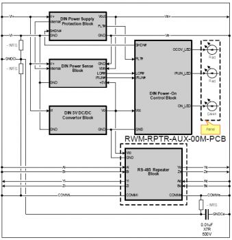
 RPTR-01M-CDIN70X110 - Block Diagram
|
Max. power consumption: 4.5 W; Form-factor: for DIN-rail mounting; Dimensions (WxH): 70x110; Protection parameters: - [Ex ib] IIA X
- Um = 15V ;
- Po = 8.8W;
- Uo = 12.6V ; Co = 7 uF;
- Io = 0.7A; Lo = 0.3mH;
- Lo/Ro=4.5*10e-5 H/Ohm;
Input/Output signal interface: RS-485/RS-485; Protection types: lightning, galvanic decoupling, idle run, over-voltage, over-current, reverse power input polarity; Indication: normal operation, errors – idle run (cable breaking), overvoltage or over-current (short circuit).
Spark protection of output power supply lines consists of current and voltage limiting with fast response. In addition to the standard protection facilities this block provides idle run detection while output power circuits are being off until a load with less than 6 kOhm is connected. Also the block provides short-current detection while the output power circuits are off until load exceeds 10 Ohm. When output power lines are being shortened and then broken the system switches from one state to another (from IR to OC) without power output ON state, so no sparks would be created in the process. The output impedance of power output source in the IR or OC/OV states is more than 5 kOhms. In normal operation (at rated load) state output resistance is sufficiently small thereby providing high efficiency and stable output voltage within wide load range. In addition to these features the block provides slow rise of current at turning on moment (i.e. soft start), which allows to avoid the sparking while connecting the terminals to the capacitive load even when the power is turned on. All lines (power and signal) are supplied with lightning protection for impulse inductions over 70 V (up to 1.5 kV). For input power lines the reverse polarity protection is provided. All components forming the protection circuits are doubled as stated in the standard for this protection class level (Ex ib II A). On the front panel the following indication is located:
![RPTR-01M-CDIN70X110 - Protection Block [Ex ib] IIA X RPTR-01M-CDIN70X110 - Protection Block [Ex ib] IIA X](/joom1/images/stories/thumbs/L2hvbWUvYWR2YW50ZXgvYWR2YW50ZXgucnUvZG9jcy9qb29tMS9pbWFnZXMvc3Rvcmllcy9JbmR1c3RyaWFsL1Byb3RlY3Rpb24vcnB0cl9sZWZ0LmpwZw==.jpg) RPTR-01M-CDIN70X110 - Protection Block [Ex ib] IIA X
RPTR-01M-CDIN70X110 - Protection Block [Ex ib] IIA X
|
ON – (green) power supply is turned on; OC/OV – (red) overvoltage or overcurrent (to high voltage at the input or short circuit at the output); IR – (red) idle run (cable breaking).
The functional block diagram is shown on the figure above. |

